@dfitzc1500
I found these (and other useful) PIDs by running a FULL “Torque Scan” (takes about 2 1/2 HOURS) on my Truck, and uploading it to my computer. Then I have extensively searched the internet on many HEX PID #’s from that list – (at least they are PID’s that RESPOND to a Torque query). I finally hit on one for the Valve Timing system and that lead me to the others. Then I added them as Custom PID’s in Torque and ran several Torque Log files on RAW DATA from them [using the straight raw formula “(A*256)+B”. Uploading that to EXCEL and playing with various formulas on the PID values, I was able to narrow down what they were for and create formulas that make gauges give reasonable results. (It’s literally like looking for a needle in a hay stack when you don’t even know what the needle looks like).
I will gladly provide PID info and settings – BUT PLEASE NOTE that this is for a 2004 Ford F150 with a 5.4L Triton (3 valve) engine. I have found there is WIDE variation in PIDs and PCM programming – even within like vehicles brands and models. And from your handle – I wonder if your vehicle might be GM, and if so, I have no idea if these PIDs – or their formulas would be relevant. If Torque Scan doesn’t include response from them – they are of no use. You can use the TEST button on any Custom Pid to see what its response looks like.
ON A 2004 Ford 5.4L 3v ENGINE – the relevant PIDs / formulas for the gauges in my previous post are:
VCTENA – Hex “16B1” = a Flag indicating “Conditions correct to enable variable valve timing” Response is one byte, bit 5 : 1=ON/ 0=OFF
OBD Mode and PID = 2216B1
Long Name = VCT Control Circuit Monitor
Short Name= VCTENA
Min = 0, Max =1, Scale factor x1
Unit type ON/OFF
Equation= {A:5}
Header/Diag Start/Diag Stop = -blank-
RCAM – Hex “16CD” = “Request Cam Retard in crankshaft degrees [twice Cam rotation degrees]”, response is two bytes signed binary “. This is the calculated retard the PCM desires to establish – from the BASE cam position – {which is probably advanced a few degrees, but I have not been able to determine how much. Thus my guage is simply shows REQUESTED RETARD – from base position of ZERO.]
OBD Mode and PID = 2216CD
Long Name = Requested CAM Retard
Short Name= RCAM
Min = 0, Max =90, Scale factor x1
Unit type= Cks Degº
Equation= ((Signed(A)*256)+B)/10
Header= 7E0
Diag Start/Diag Stop = -blank-
CAMDCR – Hex “16CF” = “VCT Solenoid Commanded Duty Cycle”, response is two bytes binary in percent duty cycle. This is the square wave duty cycle sent to the VCT Solenoids where approximately 50% holds phasers static in their present position, > 50% increases retard, < 50% reduces retard, and 0% applies maximum oil flow to the default advance position.
OBD Mode and PID = 2216CF
Long Name = CAM Duty Cycle Requested
Short Name= CAMDCR
Min = 0, Max =100, Scale factor x1
Unit type= %
Equation= ((A)*256)+B)*(100/32767)
Header/Diag Start/Diag Stop = -blank-
CAMERRR – Hex “16CE” = “-Cam Error Retard”, response is two bytes binary, This is apparently the sum of the error of both camshafts, measured in camshaft Degº – 90 deg to + 90 degº (sum of both banks if both cams were at max err). Apparently, the ECU adds the cam error in degrees for bank 1 and bank 2 ????. I’ve seen CAMERRR degrees exceed 60, but have never seen RCAM exceed about 84-85º. However the ECU can report DTCs for bank1 (P0021) and bank 2 (P0022) separately. I guess it doesn’t matter as far as CAMERRR is concerned!!! One or the other CAM is not responding to RCAM properly, or CAMERRR would be zero.
OBD Mode and PID = 2216CE
Long Name = CAM Error Retard
Short Name= CAMERRR
Min = -60, Max = 60, Scale factor x1
Unit type= Cam Degº
Equation= ((Signed(A)*256)+B)/5
Header/Diag Start/Diag Stop = -blank-
VTC?5 – Hex “16DC” = A temporary parameter name for a fifth parameter ID that I THOUGHT was related to the valve timing system. TURNS OUT – it is a two byte binary counter of “RUN CYCLES” since the last CEL RESET” So it’s nevertheless very useful.
OBD Mode and PID = 2216DC
Long Name = RUN CYCLES since CEL Reset – (or whatever you like)
Short Name= RCSCELR (or whatever you like)
Min = 0, Max = 65535, Scale factor x1
Unit type= CNT
Equation= (A*256)+B
Header/Diag Start/Diag Stop = -blank-
I’ve isolated a number of others, for the Transmission, EVAP system, Charge Motion Control (unique to the 5.4), ABS system, Temperatures and soforth. I am putting them into a spreadsheet, but unfortunately – they may not be useful to other type vehicles. I have noticed the 1600 series PID’s are largely absent in other models – even within the Ford lineup.
——-
54371019
|

 Author
 Can I Create/Access a VARIABLE in Torque Pro for a Custom PID/gauge?
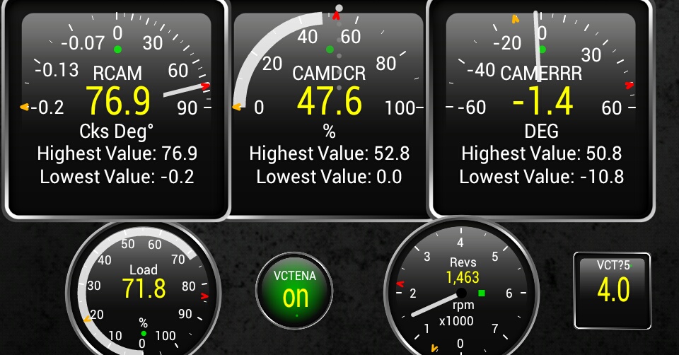
 Once again – you are absolutely correct, just as you were in solving my question in